Tuesday, November 1, 2011

Marine transmissions

Power boats and yachts need a transmission to control the power of the engine and the ability to select reverse. Marine transmissions are very similar to automotive transmissions, although a marine transmission is usually much simpler.

One of the biggest super yachts in the world Octopus

1. Explain the difference types of gear selection systems found.

There are many types of marine transmission for different types of motors. There is a variety of transmission types to suit different vessels. A large ship has to have incredible amounts of torque and low down power to drive a large propeller and accelerate a huge amount of weight.

A In outboard gear cases and stern drives

On outboard motors the most common type of gear selection system is the 'Dog clutch system ' this is a fairly simple mechanism that consists of a small dog clutch on a spline shaft which can be moved forwards and backwards from the central neutral position into engagement with the forward or reverse gears of the gear case. A small power boat does not need different ratios of  forward gears as they operate at a fairly constant speed to reach a destination, so a simple dog clutch is all that is required.


While they are simple and reliable there are some disadvantages to the dog clutch. There are no synchromesh units on a dog clutch which can make gear changes quite violent as the dog crashes into the gear. This can also damage, wear or even break the teeth on the dog clutch especially when gears are changed at high engine revolutions. The selector mechanism is also susceptible to corrosion and gear selection can be compromised.


The dog clutch can be seen in the centre.

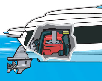
Stern drive units have a taper drive system. Drive is engaged by a brass clutch unit with a  tapered face that mates to another tapered face on the forward or reverse gear. The neutral position is in the centre and the gear is moved to engage the required gear. The advantages of a taper drive is that gear changes are very smooth unlike the dog clutch, this reduces wear on the components, however the taper drive can slip if it is worn. 


B. Inboard marine gearboxes

Inboard marine transmissions are divided up into: Hydraulic marine transmissions and Manual marine transmissions. This refers to the way power is transmitted. In a Hydraulic marine transmission drive is transmitted by the circulation of hydraulic fluid. Different gear ratios are achieved by the use of clutch packs. These clutch packs are engaged to change the engine output speed or the rotation of the output (for reverse).
Very high oil pressure is used to engage the clutch packs. Only 2 or three ratios are required from this gearbox including reverse.
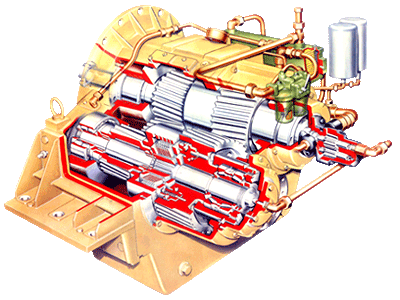
Cutaway of a Hydraulic gearbox

One of  the most common type of manual marine transmission is the planetary gear system. This system achieves different gear ratios with a planetary gear case.

Planetary Gears - Planetary gears are the most common and provide both strength and smooth operation with good resistance to torque loads.  The planetary gear systems have efficiency 65% and have a tendency to free spool when loaded, therefore a braking mechanism is needed.
Different parts of the planet gear system are held while others are allowed to rotate, this creates different gear ratios, many different ratios can be created with the use of two planetary gear cases.


A stern drive is a drive unit that is essentially the bottom leg of an outboard attached to an inboard engine. It offers the space benefits of an outboard. and the practicality of an inboard..

2 What type of gears are used in outboards and stern legs

Outboards and stern legs typically use helical gears and pinions.

A Give an explanation of why manufactures choose this type of gear.

Hellical gears are an efficient way of transferring drive, they are strong and do not wear as aggressively as spur gears, they are also quieter. The pinion transfers drive from the power head on a 90 degree angle to the propeller it has to be Strong to deal with this load.
A forward gear and pinion off a Johnson outboard

3 Explain what a duo propeller system is and how it works/operates

A duo propeller is a prop system developed by Volvo penta that utilises two contra rotating propellers to drive instead of one. A shaft and pinion from the power head drives the two propellers in opposite directions, no other gearing is necessary. The main benefit of having two propellers is the increased thrust produced, this can increase acceleration, top speed and increase fuel efficiency as well as getting a boat on the plane faster. A duo prop eliminates the lateral movement that a single propeller can give, the two propellers even each other out so the boat travels straight. Cavitation that is caused on single propellers is also reduced as the second propeller reduces slipping which creates bubbles and cavitation. Overall vibration is decreased and handling is increased.

Volvo penta duo prop

An exploded duo prop view
4Why would a v drive be used instead of a standard shaft drive system.

A V drive unit is a part of some marine transmissions that can transfer drive through tight angles. The purpose of a v drive is simply for space. Because the drive can be transferred at tight angles less space is needed for the prop shaft, this system is common for yachts where space is at a premium.

The v drive unit transfers drive underneath the engine.
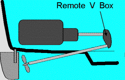
A simple yet effective v drive diagram

5 Compete a jet unit with a surface drive unit and give reasons why you would choose one system over the other.

Jet units were invented by New Zealander Bill Hamilton for navigating shallow south island rivers.
A jet unit operates on the function of drawing in water and accelerating the water through impellers out of a nozzle which can be controlled to turn the boat. The advantages of a a jet unit are: It can operate in very shallow water, Very high acceleration, good handling, and savings in space. A jet boat can operate in shallow water as there is no propeller to be caught on the ground some jet boats can operate in just 7.5cm of water. Acceleration and handling are very responsive as the water jet can be directed at will, and space is saved by having the jet unit on the transom of the boat. A jet unit is disadvantaged by its fuel efficiency which can be greatly affected if the jet intake is clogged by something, a jet unit is also affected by engine mismatch greater that a propeller boat.

Diagram of a jet unit

Jet unit can be seen on the back of the boat

Surface drive units are a conventional propeller which is positioned on the surface of the water. Half of the propeller is out of the water and half is submerged. Having the propeller at the surface level reduces drag and reduces the vessels draft, making the surface drive suitable for many applications where the owner is looking to reduce fuel costs, increase speed and create a more efficient vessel. A surface drive can deliver very high performance and is relatively simple, however it is disadvantaged by more drag and less acceleration and handling than a jet unit. The surface drive can also be unsafe as the propeller is out of the water and could make the boat unstable at high speeds due to the propeller slapping the water which increases lateral forces.


For these reasons i would choose a jet drive unit over a surface drive unit. It is reliable and provides very good performance, whilst being developed and improved by company's worldwide. Also I'm a New Zealander so I'm being patriotic.

Jet sprint. Ridiculous.

http://www.ehow.com/how-does_5336911_volvo-outdrive-duoprop-works.html

http://www.volvopenta.com/volvopenta/na/en-us/marine_leisure_engines/drives/dph_duoprop/the_benefits_of_duoprop/pages/the_benefits_of_duoprop.aspx

http://www.marinepartsexpress.com/promo/duoprop.html

http://en.wikipedia.org/wiki/Sterndrive

http://en.wikipedia.org/wiki/Dog_clutch

http://en.wikipedia.org/wiki/Outboard_motor

http://en.wikipedia.org/wiki/V-drive

http://en.wikipedia.org/wiki/Jetboat

Monday, October 3, 2011

Manual Trasmission

 A manual transmission is a type of trasmission that requires the driver to change gears. It is a relatively simple system and is widespread in the automotive industry. A manual gearbox is engaged by a driver operated clutch and gears are selected with a gear stick.

 A manual gearbox

1. What type of gears are used for reverse in a manual gearbox?

 Reverse gears in a gearbox are straight cut gears, meaning the teeth are straight. reverse gears are usually small ratios as a car does not need to travel in reverse at high speed.

A set of reverse straght cut gears (idler, driver and driven.)

a. Give an explanaiton for your choice

Straight cut teeth are used on reverse gears because spur gears are far easier to mesh together than helical gears. In a lot of cases all of the foward gears in a modern gearbox are helical (angle cut teeth), Because reverse gears have to engage with an idler, how the gears mesh is critical. The disadvantage's to spur gears are: Spur gears wear more as only one tooth is in contact while the gear is spining, and they make more noise than a helical gear.


2. What type of gears are used for all foward gears in a manual gearbox?

Helical gears are used in the foward gears of a gearbox. These gears have angled teeth which means that more surface area and more teeth are in contact at one time while the gear is spinning. Herring bone type gears are used in large applications like trucks or earthmoving equipment, these gears can take the very high amounts of load required in a large application however they are more complex and more expensive to manufacture.


A herringbone gear

A. Give an explanation

 Helical gears are stronger and quieter than spur gears. Because of the amount of teeth in contact with the meshing gear a helical gear does not wear as agressively as a spur gear, giving them a longer lifespan. As a gearbox is usually in a foward gear lifespan is critical.

3. What is the purpose of a synchromesh unit.

A synchromesh unit is a part of the geartrain, its job is to make the changing of gears smoother, this is done by sychronising the teeth of the two gears that are about to be engaged. This synchronation of the gear teeth ensures the gears are travelling at the right speed and the gear teeth are in the right position. A synchromesh unit can save the gear teeth from damage and extend the life of the gearbox because it is saved from violent gear changes. If the synchromesh unit is damaged then gear changes may be clunky or may not change at all.

A simple Synchromesh diagram

A. Explain the operation of a synchromesh unit?

A synchromesh unit has to smooth the changing of gears by lining up the gear teeth and to ensure the gears are running at the same speed. This is achieved by a unit called a baulk ring. This unit is positioned on the geartrain between gears, when there is a gear change the baulk ring engages the next gear with a tapered face that grips to another tapered face on the gear and makes them travel at the same speed. There is a small clearance on the baulk ring which allows it to rotate and let the teeth of the rings line up. Gears can now be changed with ease.

 Position of the baulk ring on the geartrain.

Synchro or baulk ring

C. How do we check a baulk ring for serviceability?

Because a Baulk ring is under a high amount of stress it can be damaged. The baulk ring has to deal with stress of engaging a gear with a tapered face especially at high speeds. and over time the stress could warp and chip the teeth of the ring. A damaged baulk ring may not engage properly or could damage other gearbox components.

Wear to the tapered face of the baulk ring

4. What type of bearings do we find in gearboxes?

A gearbox needs many types of bearings to run. Caged roller bearings are used on the main and counter shaft. These bearings allow smooth rotation movement of the geartrain. Thrust bearings are used to keep the shafts from 'floating'. lateral movement of these shafts can damage the gears. Needle bearings are used on the inside of shafts, and flat caged needle bearings are used in the final drive assembaly.

Gearbox thrust bearing and tapered roller bearings.


5. Give an explanation of a gear ratio.

A gear ratio is the difference in speed of two connected shafts or gears. The gears travel at different speeds because of the amount of teeth on the driver and driven gear and the size of the gear. A gear ratio is measured in the amount of revolutions one shaft does in one revolution of its connected shaft. A ratio of 2:1 means that the shaft does two revolutions in one revolution of its connected shaft. Small gear ratios allow high speeds, while high gear ratios multiply the torque produced.  Gear ratios are important in controlling an engine and keeping the engine in its optimum operating speed.


Tuesday, September 20, 2011

Engine Reflections

Cylinder Head

Toyota 1600 4A-FE

The cylinder head has to deal with very high stress and temperatures. Because of this the parts that make up the cylinder head have to be checked for damage, and measured to make sure they are within the manufacturers specifications.

Inspection of the cylinder head

The face of the cylinder head is checked visually for damage like: chips, scratches, corrosion, broken edges, and broken threads. The face of the cylinder head is also checked for warpage by placing a straight edge across lengths of the face, a feeler gauge checks the warpage of the face. This kind of damage could effect how the cylinder head mates with the cylinder block or possibly make the engine lose compression, which can shorten the life of the head gasket.

Checking a cylinder head for warpage

Valve Guides

Valve guides provide support and lubrication. for the valve as it travels up and down. Valve guides are visually inspected for damage like bending or chips. The guides are also measured in diameter at 6 locations with a telescopic gauge and micrometer to determine the amount of wear, taper and ovality. Because of the up and down movement of the valve in the valve guide, the guide can taper at the top and become oval as the valve has a thrust side where more wear happens. if a valve guide is bent then the valve can suffer excess wear.


Valves
 The condition of the valves is very important as their operation is vital to engine operation valves operate under very high temperatures and ave to been tough to cope with forces.. The valves are visually inspected and measured for wear, cuts, carbon build up and operation. Valve stems are measured with a micrometer at 3 positions, the top middle and bottom. The top and bottom have the largest amount of wear as it is the largest thrust area. the stem measurement is subtracted from the valve guide measurement to find the valve oil clearance. If this clearance is too small the valve could seize.


Valve Collets and keepers

Valve collets and keepers hold the valve onto the valve spring. if they are damaged or bent then the valve could come off the spring and it would no return to the valve seat.


Valve seats

The valve seats are inspected for damage, wear, seat angle and carbon build up. The valve seat seals the valve with the cylinder head so that no compression is lost. If the seat is damaged or worn the valve may not sit properly. The angle of the seat also determines how well the valve sits. Small carbon deposits that build up from combustion can collect on the valve seat and make the valve not sit properly.

Carbon and damage on a valve seat


Valve Spring

The job of the valve spring is to return the valve to the valve seat after it is opened, and hold it there. The forces on the spring can bend the spring which affects its operation. This is measured with a set square and vernier calliper. if the valve spring is bent by more than 2.0 mm then it should be replaced as the spring may not be returning the valve to its seat properly. The valve springs are also checked for: free length, installed height and spring tension. All of these checks ensure that the spring is working properly. Spring tension is measured on a valve spring pressure tester, the valve spring can lose it's tension and elasticity over its lifetime and its ability to return the valve to its seat.
Camshaft

The camshaft is responsible for the opening and closing of the valves, any amount of damage or wear to the camshaft can affect engine timing and engine operation. The camshaft is visually inspected for cuts, metal imperfections, or scuffing on the cam lobe. The camshaft lobes are measured for lift and wear. If they are worn enough then the timing of opening the valves would be affected greatly.

Lift is measured by subtracting the base Circle from the base circle and lobe lift.

Camshaft journals are visually inspected for wear and damage. Damage to the journals could make the camshaft wobble or have increased wear. Camshaft journals are measured for wear as well. If a camshaft bearing is tapered or has become oval from wear then it's operation will be affected, the journal may not spin true which may affect timing. The Journals are measured at both ends to calculate the taper from one end to the other, A high amount of taper could mean that the journal is running unevenly. Ovality is measured with a micrometer on the y and x axis, ovality is the wearing of the circular journal into an oval shape, this can make the journal and camshaft run poorly. Cylinder head bearings on modern engines are usually integral and cannot be replaced, leading to the entire head being replaced.

Camshaft Run out

Camshaft run out occurs over time as the stresses on the camshaft journals wear and twist until the journal has points of wear. this also contributes to taper and ovality of the journals. Run out is measured with a DTI gauge that is positioned on the journal to record the slight changes in wear.


Camshaft bearing oil clearance


The bearing oil clearance is the space that oil can travel through to lubricate the bearing. If the oil clearance is too large then the camshaft will not rotate smoothly, if the clearance is too small not enough oil can enter for lubrication and the camshaft may seize due to the immense heat the cylinder head works at. Oil clearance is measured with a plasti


Bucket pad thickness

On some DOHC engines the camshaft lobes follow a bucket pad type system which is on top of the valves. These pads which are case hardened to lengthen their life span and protect from the constant wearing of the camshaft lobe acting upon it. The valve clearance and timing can be adjusted by changing the height of these pads. If the pads are severely worn then they may not be opening the valve properly, affecting the timing and performance of the engine. Bucket pads are measured with a micrometer and along with the valve clearance measurement are used to figure out the thickness of the replacement pad.

Simple bucket valve system

More complicated variable valve timing mechanism

Camshaft End float

Camshaft end float is the lateral movement of the camshaft while it is capped down. Every camshaft has a small amount of end float, this amount can be increased as the engines gets older by wearing the thrust bearings that stop lateral movement. These bearings can easily be replaced. Too much end float can make the camshaft wear more aggressively as it may be out of place laterally. End float is measured with a DTI gauge positioned on the end of the camshaft as the camshaft is moved back and forth.

Jesus!


Thursday, September 15, 2011

Engine reflections

Reflections need to be made on the practical work done in class to ensure that the work is understood.

Toyota 1600cc

Engine Block

Measuring the Piston:
The piston is measured in diameter at 10-15mm from the bottom of the piston skirt on both axis. They are also visually inspected for damage and wear. Small chips, scuffing of the piston, carbon buildup, and scratches can effect the pistons life and operation. The measurements are done to determine if the piston has been worn, tapered or become oval in shape. all of these can effect the engines operation.


Inspection of the cylinder bore:

The Cylinder bore is inspected for wear and damage. The cylinder bore can scuff and score from the movement of the piston, this can cause more damage to the piston or piston rings and to the hardening layer in the cylinder bore. Wear is measured with a bore gauge at 6 positions on the bore. At the bottom middle and top on both the y and x axis, this is to check for taper and ovality of the cylinder bore. The top of the bore is the most worn, and one axis of the bore is worn more than the other because it is the thrust side of the crankshaft movement. This is also used with the measurements from the piston to calculate the piston clearance.


Piston rings:

Visually inspected for damage and wear. Piston rings can snap and cause a lot of damage to an engine, also if they do not work correctly pressure from the combustion chamber can go past the pistons leading to poor combustion. Carbon deposits can build up behind piston rings and restrict there movement and operation.
Ring side clearance: Checked with a feeler gauge, if a worn or wrong ring is fitted then they do not work properly.
Groove depth: Carbon buildup can reduce groove depth.
Ring end gap: Measured by putting the piston in the cylinder with the ring on and measuring the gap. If the ring gap is too big (from wear) compression can be lost.

Worn piston ring

Connecting rods:

Con rods are under huge strain and can suffer twisting and bending from the forces of piston movement and transmitting linear motion to rotational motion. If a con rod is bent or twisting it can increase the amount of wear on the engine and piston, or even break under strain. Bending can be repaired to a certain degree. Twist is measured on a flat face with a special tool.

Bent con rods from immense strain.

Crankshaft

The crankshaft is visually inspected and measured to determine if it is damaged or worn. As the crankshaft has a lot of force applied on it, It can suffer wear and surface damage. Cuts on the crankshaft can damage the con rod bearings. and if the wood roff key is damaged, components may not work properly. The Crankshaft journals are measured for wear taper and ovality. If the journals are worn, the crankshaft may not spin correctly or the con rods travelling on the big end journals could wear more aggressively. Measurements are taken (by micrometer) at each end of the journal and at both axis. Crankshafts are also measured for Deflection. This is the 'twisting' of the crankshaft that comes from the torque applied to it over time. It is measured with a DTI gauge and small measurements are recorded.

A lot of force is needed to break a crankshaft.

Cylinder block:

The cylinder block is visually inspected for cracks, corrosion and general damage sustained during use . A crack or corrosion can compromise the strength of the block and make it degrade faster. The Distortion of the cylinder block face is measured with a straight edge and a feeler gauge across different parts of the face. If the Cylinder block face is distorted then the cylinder head may not sit properly or combustion could be lost.
Broken bolts or threads can make the block weaker.

Timing gears, sprockets and belts. 

Because the timing gears are essential to the running of the engine, they are important to check for damage and wear. Worn gears could upset the timing or break. A worn belt or chain has the potential to wreck an engine if it breaks. Chains are checked for worn links, corrosion or tension, and belts are checked for fraying, cracks,corrosion, brittleness and tension. 

A broken Cam belt

And the results, valves left open can be bent by rising pistons.

Core plugs: 

Core plugs are checked to ensure they are doing their job, plugging holes in the block made during casting, and also provide a pressure release if the water in the jacket freezes. If they are corroded they could leak. If they fall into the water jacket they can obstruct water flow.

Oil pump

The oil pump pumps oil from the sump to parts of the engine that need lubricating. If the oil pump breaks the engine could seize due to lack of lubrication. The clearances of the pump impeller and housing are measure with a feeler gauge to ensure they are in manufactures specifications and are not leaking.

A rotary oil pump that has broken its housing.

Bearings and caps

The crankshaft and con rod bearings are important as they help reduce wear on the engine and increase its lifespan. They can be replaced instead of larger parts. Bearings are checked for visual damage and oil galleries are not clogged.

Main bearing and big end bearing oil clearance

Measured with a palsti gauge, the plastigauge measures the gap for oil to pass through and lubricate the bearing, if the gap is too small the bearing could seize.

Crankshaft float

The thrust movement of the crankshaft is called crankshaft float. this reduced by thrust bearings. The float is measured with a DTI gauge. Too much float can wear the crankshaft or result in poor operation.

Con rod play

Con rod play is the thrust movement between the conrod and crankshaft big end bearing. A feeler gauge is placed in the gap to measure the thrust of the con rod. if the gap is too big the con rod can be under more stress and the piston can be worn more.